Asked by Nyiah Smith on Jun 17, 2024

Verified
The diagram shown is that of a
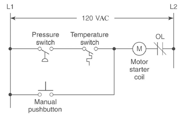
A) hardwired relay schematic.
B) ladder logic program.
C) input module schematic.
D) output module schematic.
Hardwired Relay Schematic
A diagram that represents the physical wiring and logic connections of relays within a control system.
Ladder Logic
A graphical programming language used in programmable logic controllers (PLCs) that emulates electrical relay logic circuits.
- Evaluate and understand the wiring diagrams and schematics associated with Programmable Logic Controllers.

Verified Answer
JP
Jennifer PrudhommeJun 19, 2024
Final Answer :
A
Explanation :
The diagram shown is a hardwired relay schematic because it represents physical connections between relays, switches, and other components. It is not a ladder logic program, input module schematic, or output module schematic because those types of diagrams would look different and represent different types of components and connections.

Learning Objectives
- Evaluate and understand the wiring diagrams and schematics associated with Programmable Logic Controllers.